In optical sensor systems, filters serve as critical components that shape and control the light reaching the sensor. Whether blocking unwanted infrared radiation, mimicking human visual perception, or diffusing incoming light for uniform measurement, filters directly impact sensor performance and data quality. The mechanical design and integration of these filters requires careful consideration of optical properties, physical placement, mounting methods, and environmental factors.
This article explores the key principles of filter selection and placement in optical sensor packaging, covering common filter types, design considerations, and best practices for mechanical integration.
Common Filter Types in Optical Sensor Systems
IR-Cut Filters
Infrared cut filters represent one of the most ubiquitous filter types in visible-light imaging systems. Silicon-based image sensors inherently detect light well into the near-infrared spectrum (up to approximately 1100nm), far beyond human vision's upper limit of around 700nm. Without filtering, this IR sensitivity would corrupt color accuracy, causing images to appear washed out with incorrect color balance.

Optical filter window (bottom right) in front of a sensor
IR-cut filters typically consist of thin glass substrates with specialized dielectric coatings that reflect or absorb infrared wavelengths, while transmitting visible light. The coating design creates a sharp transition between transmission and blocking, usually positioned between 650-700nm. Some advanced designs incorporate multiple coating layers to achieve steeper cut-off slopes and better out-of-band rejection.
An important consideration with IR-cut filters is their behavior across the entire spectrum. While designed to block IR, these filters often show increased transmission in the far-infrared region, which can affect thermal management in some applications. Additionally, the angle-dependent nature of dielectric coatings means the cut-off wavelength shifts with incident angle, potentially causing color variations at image edges in wide-angle systems.
 Image of runway before and after installing infrared camera designed for Max Viz
Photopic filters
Photopic filters are specialized spectral filters engineered to match the human eye's daytime vision response curve (CIE 1931 photopic luminosity function). These filters weigh incoming light according to human brightness perception, with peak sensitivity around 555nm (green) and reduced response toward the red and blue ends of the spectrum.
In ambient light sensors and exposure measurement systems, photopic filters ensure the sensor output correlates with perceived brightness rather than raw radiometric power. This human-centric measurement is essential for applications like display brightness control, where the goal is matching human visual comfort rather than absolute light intensity.
Manufacturing photopic filters requires precise control of spectral transmission characteristics. Some implementations use absorptive glass formulations, while others employ thin-film coatings. Advanced designs may combine multiple filter elements to achieve closer approximation to the ideal photopic curve. The mechanical design must account for potential angle sensitivity, as some photopic filter implementations show spectral shifts with incident angle.
 Image of a human iris.

Graph of the photopic response of the human eye.
Diffusers
Diffusers transform directional light into uniform, angle-independent illumination. In optical sensor applications, they serve multiple purposes: eliminating hotspots, averaging spatial variations, and creating Lambertian light distribution for cosine-corrected measurements.
Lambertian diffusers represent a special class that scatters light according to Lambert's cosine law, where apparent brightness remains constant regardless of viewing angle. This property proves invaluable for ambient light sensors that must respond consistently to light from any direction. The diffuser ensures the sensor measurement represents total incident light rather than just the component aligned with the sensor axis.
Diffuser materials range from ground glass and opal glass to engineered polymers with controlled scattering properties. The degree of diffusion must be carefully balanced – too little leaves angular dependencies, while excessive diffusion reduces light throughput and may blur spatial information in imaging applications. Surface texture, bulk scattering properties, and thickness all influence diffuser performance.
 A beam of light incident on the diffuser, is refracted into the substrate and refracts on exit, achieving the designed diffusion.
Critical Placement Considerations
Optical path integration
Filter placement within the optical stack significantly impacts system performance. The fundamental principle is maintaining an unobstructed optical path while achieving the desired spectral modification. For imaging systems, this means positioning filters where they affect all light reaching the sensor without introducing aberrations or vignetting.
In many camera modules, IR-cut filters mount directly above the sensor package, either bonded to the cover glass or held in a separate frame. This position ensures all light passing through the lens system encounters the filter before reaching the sensor. The proximity to the sensor minimizes the filter size requirement and reduces the risk of stray light bypassing the filter.
For non-imaging sensors like ambient light detectors, filters often integrate directly into the package window. Manufacturers may apply photopic filter coatings to the package glass or incorporate absorptive filter glass as the window material itself. This integration simplifies assembly and ensures consistent optical properties.

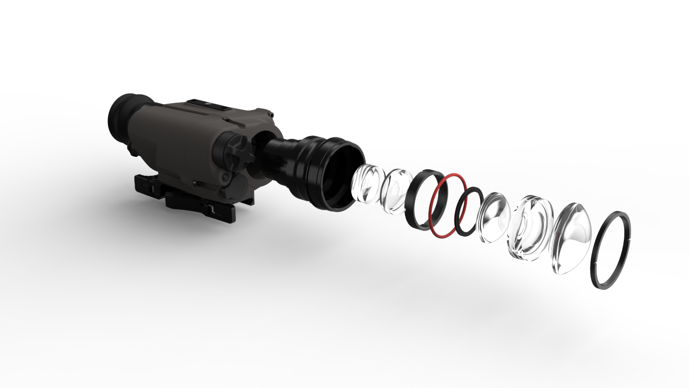
Exploded view of camera, filters and lenses in an optical system
Angular Considerations
The incident angle of light on filters affects their performance, particularly for interference-based designs. As light deviates from normal incidence, the effective optical path through coating layers changes, shifting spectral characteristics. This angular dependence becomes critical in wide field-of-view systems where edge rays may encounter filters at steep angles.
To minimize angular effects, some designs incorporate slight filter tilts (typically 2-5 degrees) to prevent direct reflections back to the sensor while keeping average incident angles small. Anti-reflective coatings on filter surfaces further reduce ghost images and improve light throughput. In extreme wide-angle systems, specialized filter designs with reduced angular sensitivity may be necessary.
 Observed intensity (photons/(s·m2·sr)) for a normal and off-normal observer; dA0 is the area of the observing aperture and dΩ is the solid angle subtended by the aperture from the viewpoint of the emitting area element. Source Inductiveload - Own work, Public Domain.
Spacing and Air Gaps
The distance between filters and adjacent optical elements requires careful optimization. Too small a gap risks mechanical interference from thermal expansion or assembly tolerances. Excessive gaps can enable internal reflections and increase package size unnecessarily.
A typical approach maintains air gaps of 0.1-0.5mm between filters and sensor cover glass, achieved through precision spacers or controlled adhesive bond lines. This spacing prevents direct contact that could damage delicate sensor coatings while minimizing the volume where contaminants might accumulate. Some designs eliminate air gaps entirely by optically bonding filters to adjacent elements, though this approach complicates serviceability.

A side view of a mobile phone showing minimized air gaps between glass and internal components.
Learn more about about Designing for glass in consumer electronics
MECHANICAL MOUNTING METHODS
Direct Bonding
Adhesive bonding offers a compact, permanent mounting solution for filters in optical assemblies. The adhesive selection proves critical – optical-grade materials must provide clear, stable bonds without outgassing volatiles that could fog optical surfaces. UV-curable adhesives enable precise positioning before curing, while thermally cured epoxies may offer superior long-term stability.
The bonding process typically applies adhesive only at filter edges, keeping the clear aperture free of any material that might affect light transmission. Precise dispensing equipment ensures consistent adhesive beads that secure the filter without excess material squeezing into optical areas. Some designs employ black adhesives for edge bonding, providing additional stray light control.
Frame Mounting
Mechanical frames offer advantages for filters requiring periodic replacement or precise positioning. Frames may use spring clips, threaded retainers, or snap-fit designs to hold filters securely while enabling removal. This approach proves valuable in research instruments or high-end imaging systems where filter changes support different measurement modes.
Frame design must account for thermal expansion differences between filter materials (typically glass) and frame materials (often metal or plastic). Compliant interfaces like elastomeric gaskets accommodate differential expansion while maintaining position. The frame geometry should provide uniform support around filter edges without inducing stress concentrations that could cause breakage.

Soft mounting for sensitive component and glass bending across height difference increases chances of breakage.
Solution is a rigid shield added allowing for gentle bending of glass surface without stiffness transition. Source: Designing for glass in consumer electronics.
Integrated Package Solutions
Modern sensor packages increasingly integrate filters directly into their construction. Wafer-level packaging processes can deposit filter coatings on cover glass before sensor assembly, creating compact, cost-effective solutions. Other approaches mold filter holders directly into plastic packages or incorporate filter glasses as structural package elements.
These integrated solutions offer excellent mechanical stability and eliminate separate filter assembly steps. However, they reduce flexibility for filter customization and may complicate inventory management for products requiring different filter options.
Environmental Protection and Reliability
Contamination Prevention
Cleanliness during filter assembly proves paramount, as any particles trapped on filter surfaces create permanent image artifacts. Assembly typically occurs in controlled environments with filtered air flow. Operators use specialized handling tools to grip filters only at edges, preventing fingerprints or contamination of optical surfaces.
Pre-assembly cleaning may involve ultrasonic baths, vapor degreasing, or plasma cleaning to remove organic residues. Inspection under bright lights or laser scatter detection helps identify particles before final assembly. Some production lines incorporate automated optical inspection to verify cleanliness standards.
Design Optimization Strategies
System-Level Integration
Successful filter integration requires considering the entire optical system rather than treating filters as isolated components. Ray tracing analysis should include filter effects, accounting for spectral changes, reflections, and potential ghost images. Tolerance analysis must encompass filter thickness variations, tilt errors, and spectral variations between batches.
Performance Verification
Comprehensive testing validates filter integration success. Spectral measurements confirm proper wavelength selection, while imaging tests verify uniform performance across the field of view. Environmental testing ensures mechanical stability under operating conditions. Key metrics include:
- Spectral transmission curves at multiple field positions
- Image quality metrics with and without filters
- Thermal stability of focus and color balance
- Mechanical shock and vibration resistance
Integrating Filters for Optimal Performance
Filter selection and placement in optical sensor systems demands careful attention to both optical performance and mechanical integration. Success requires understanding filter characteristics, optimizing placement within the optical stack, implementing robust mounting methods, and ensuring long-term reliability. By following the principles and practices outlined in this article, designers can create sensor packages that deliver consistent, high-quality optical performance throughout their operational lifetime.
The ongoing evolution of sensor technology and miniaturization continues to drive innovation in filter integration methods. Future developments may include active filter systems, tunable spectral responses, and further integration at the wafer level. However, the fundamental principles of maintaining optical quality while ensuring mechanical robustness will remain central to successful filter implementation in optical sensor systems.
Learn about our Opto-Mechanical projects.
