Optical devices and their supporting circuits generate heat, and they are also affected by the external environment. Managing heat is a crucial part of the Opto-mechanical design process to keep the device functioning within spec and to maintain image quality. Camera sensors can exhibit more noise at temperature excursions, and optical focus can shift due to the coefficients of thermal expansion (CTE).
A wide range of display technologies, such as Digital Light Processing, Liquid Crystal Display, Liquid Crystal on Silicon, OLED Microdisplays, MicroLED Projectors, and Laser-Based Display Technologies all exhibit wavelength-temperature dependence such that running off-target temperature will decrease the useful output. Both display and sensor systems undergo changes in effective focal length (EFL) due to the coefficient of thermal expansion (CTE, dx/dT) of the structures, and also refractive index variation with temperature, (dn/dT). Thermal management in optical system design involves careful selection of materials, geometry, and cooling features.
Material Expansion & Compensation
Different parts of the optical stack expand at different rates when temperatures change. To maintain image quality under thermal load, minimize the difference in expansion between lens, mount, and sensor where possible. This is known as athermalization.
For example, a typical PCB or organic substrate expands more than a silicon sensor die, and a plastic lens barrel might expand much more than a glass lens. If unchecked, these expansions can cause the lens shape or lens-to-sensor distance to change (defocusing the image) or induce stresses (bending the sensor or cracking the lens). Hygroscopicity, or the ability of a material to absorb moisture, can also lead to dimensional changes in parts.
 Optical system showing change in EFL with Temperature
To address this, engineers strive to use materials with low and compatible coefficients of thermal expansion (CTE) and low hygroscopicity, or introduce compensating elements. One approach for low-cost consumer devices is using a matched CTE for the lens mount – for instance, the lens barrel might be made of liquid crystal polymer (LCP), which has relatively low CTE for a polymer, to better match the expansion of the lens and sensor.
In higher-cost/performance systems, more advanced compensation might involve using two or more materials in a housing with CTEs and lengths selected to offset the change in effective focal length of the optical stack over the operating temperature range.
Close cooperation between optical engineers and mechanical engineers should be maintained to ensure that the expected change in EFL for the optical stack and the thermal growth of the housing structure match.
When environmental variation is low, the solution might simply be to focus the module at an intermediate temperature so that the maximum defocus at extremes is bounded. For critical systems, feedback-based focus (like moving lens elements via actuators as temperature changes) can be implemented, but this complicates packaging. Most consumer devices avoid that and rely on passive athermalization to make the optics insensitive to temperature changes.
Further Structural Considerations
Beyond the normal operating case, the device needs to survive the effects of the non-operating environmental conditions, such as storage temperature extremes and shock and vibration requirements. These conditions can lead to relative movement of optical elements and/or peak stress conditions that could cause parts to break.
 Aluminum heatsink on PCB board
Heat Dissipation Strategies
In many cases, a sensor itself doesn’t consume huge power (a camera sensor might draw a few hundred milliwatts), but, if it’s part of a larger system (like in a phone near a hot processor or an IR sensor with on-board illumination), it can get hot. With high-speed sensors and most displays, significant heat needs to be drawn away to keep within the optical specification. Additionally, in space-contained applications, such as in AR designs, as little as a few watts of thermal power can be a challenge to dissipate. Common thermal management techniques in optical packages include:
Heat Sinks & Spreaders
Attaching a small heat sink or metal plate to the sensor or its PCB can help conduct heat away. For instance, machine vision cameras often mount the image sensor on an aluminum core or have a heat sink on the back of the PCB. The idea is to increase the surface area and spread heat to the air.

Fan and heatsink mounting for LED-based lighting with thermal simulation
In compact consumer modules, a dedicated heat sink might be replaced by using the device’s chassis. In these devices, average electrical power is capped by the thermal limits of low surface area and low external temperature comfort limits. Thus, a high coefficient of thermal spreading is required. Some consumer electronics designs use the metal camera bezel or frame as a heat spreader for the camera module.
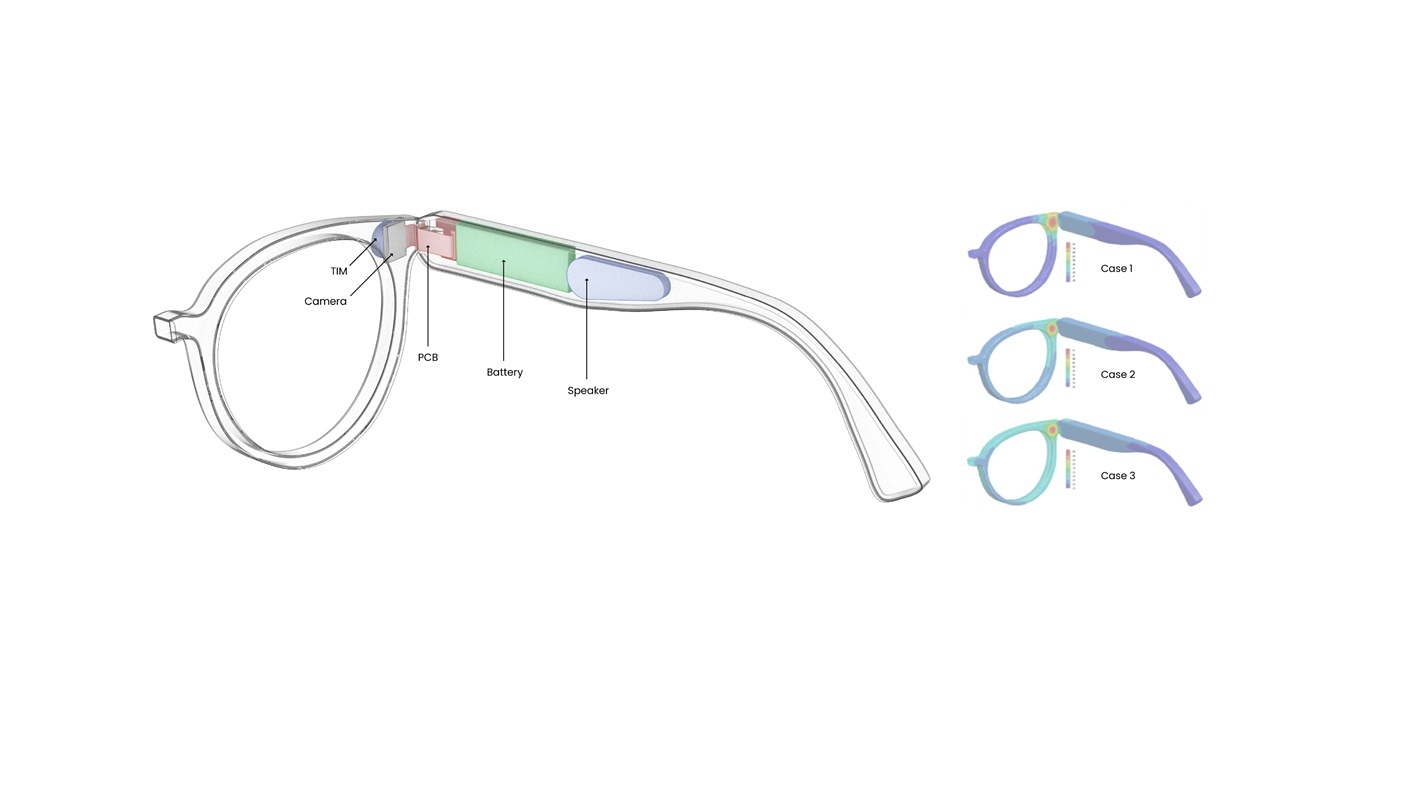
Consider the comparison between using standard plastics and die-cast zinc for the outer frame and a silicone pad vs an alumina TIM at the camera module in a pair of augmented reality glasses.

AR glasses with components and thermal simulation results by case. All cases include T_ambient = 20 C and 350 mW total input power. All Surface Plot 1: contours external Surface Plot 2: Constours.
|
|
Case 1 |
Case 2 |
Case 3 |
|
External Material |
PC |
Zinc |
Zinc |
|
Thermal Interface Material Camera |
Silicone Rubber |
Silicone Rubber |
Alumina |
|
T_max_camera [C] |
128 |
101 |
89.3 |
|
T_surf_avg [C] |
25.8 |
25.9 |
25.8 |
|
T_surf_max [C] |
82.3 |
57.1 |
49.7 |
|
Coefficient of Thermal Spreading |
9% |
16% |
20% |
Copper foil or graphite sheets are widely used as well – these can be stuck on the module to channel heat to a larger area. Pyrolytic graphite has excellent in-plane thermal conductivity and very low thickness, making it ideal to fit into tight spaces as a heat spreader. Thin copper tapes serve a similar role. By spreading heat across a larger area, these materials prevent hot spots and allow the heat to eventually dissipate through the device casing.
In industrial or scientific applications, cold plates with chilled water, coolant immersion, thermoelectric or two-phase cooling such as heat pipes, vapor chambers, and refrigerant-based designs, can be used to spread and extract heat. Thermoelectric coolers (Peltier devices) have even been used in scientific cameras to actively cool image sensors for low noise; however these require significant power and are beyond typical product design.
High Thermal Conductivity Substrates
Some sensor packages or boards use ceramics like Aluminum Nitride (AlN) or Aluminum Oxide for better thermal performance. AlN, in particular, has a high thermal conductivity (on the order of 170 W/mK), and can be used as the substrate on which the sensor is mounted, effectively acting as a built-in heat spreader.
While this approach is more typically used in laser diode or display module packaging, it is also a viable option for optical sensors, particularly infrared or spectroscopic sensors that may include heaters.
There are also patented socket designs that draw heat from image sensors using an aluminum body. In short, the PCB or carrier choice can significantly impact thermal flow – FR4 PCB substrate board is a mediocre thermal conductor, whereas metal-core or ceramic boards can significantly drop sensor temperature by conducting heat to the housing.
Advanced Cooling (Vapor Chambers, Heat Pipes)
In extreme cases or specialized equipment, one can employ tiny heat pipes or vapor chambers to move heat. A vapor chamber is a flat, sealed, evacuated device with fluid that can rapidly spread heat by undergoing physical phase changes; a heat pipe is similar but tubular.
 Copper heat pipes integrated into a circuit board.
These aren’t commonly found in small sensor modules due to cost and size, but some advanced smartphones and VR devices use miniaturized versions to cool cameras or projectors. There are exciting new developments with polymeric versions as thin as 0.1 mm with thermal conductivity as high as 25 kW/m-K that are foldable and beat graphite on cost and weight
If an optical sensor is part of an AR headset that generates a lot of heat, a heat pipe could route heat from the sensor area to a cooler part of the chassis.
The takeaway for most designs is to provide a thermal path from the sensor to the outside. This could mean potting the sensor in a thermally conductive encapsulant or simply ensuring there is a metal path from the sensor PCB to the device enclosure. Avoid trapping the sensor in a thermally insulating pocket with no way to shed heat.
If using a sealed module, consider a metal body or insert that touches the sensor package and extends to the exterior. Each of these strategies can be mixed as well – e.g., a graphite sheet from the camera module to a device heat spreader, plus a metal camera bump that radiates heat.
Comfort and Safety in Consumer Devices
An often overlooked aspect of thermal management is the external temperature of the device where the sensor is located. In consumer electronics, there are guidelines for how hot surfaces can be when touched by users. Generally, sustained skin contact should not exceed around 45 °C for comfort (even lower for prolonged contact). This means if your sensor’s heat sink doubles as an external cover (like a metal camera enclosure on a phone), you must ensure it won’t get too hot to touch.

Handheld electronic device thermal free body diagram.
 Thermal simulation results of skin temperature when holding a handheld device.
Even if the internal components can survive 80°C, the user’s fingers won’t appreciate a 50°C metal ring on their camera. Regulatory standards and ergonomic studies set limits in the 40–45°C range for consumer device touch temperatures. Thus, designers must sometimes throttle performance or spread heat more to keep external parts at safe levels. When selecting materials and methods, consider their thermal conductivity and specific heat – metals like aluminum are great for spreading heat but also can transfer heat to touch quickly, whereas plastics keep heat localized (good for touch, bad for shedding heat). Often a combination (metal inside/environment facing, plastic outside/user touching) yields a device that protects the sensor but insulates the user from heat.
Additionally, high temperatures can affect materials long-term – for example, if an adhesive is consistently exposed to 60–70°C, its lifespan may shorten. Consumer products typically design for an operational range (e.g. 0–35°C ambient), and ensure that even at max ambient and usage, the internal sensor stays within its spec (maybe under 85°C) and the exterior remains cool enough.
Outside of opto-mechanical design, software limiting (reducing sensor frame rate/computing if overheating) and driving towards low-power designs in the electrical hardware design complement the overall effort.
In summary, thermal design is about cost, performance, and user experience. A well-packaged sensor will not only keep it’s cool to maintain image quality but also ensure the heat it does dissipate is routed in a way that doesn’t compromise the device or comfort.
Learn about our projects and process.
