We use various optical tools, including spectrometers and filters, to measure and characterize devices, ensuring accurate spectral energy readings and color balancing.
We need these tools for several reasons – first, to ensure when we design something – say a sensor device – the device reads light at an accurate level specified by the requirements brief. For example, if the brief calls for an infrared sensor, we need to ensure it only reports infrared light.
Second, we must be certain the device can be reproduced consistently – to do that we measure the device’s characteristics and create a reference unit. Then, we calibrate all the subsequent units we're building to that.
Light characterization and optical testing capabilities.
At Sherpa we have a number of projects that focus on integrating sensor packages to capture and process light across different spectrums. In some cases, we create pre-production units for testing and field application. To ensure precision and uniformity, we rely on advanced optical testing tools such as monochromators and polychromators.
Monochromator
One of the ways we characterize our reference unit is to measure the frequency response of the device.
For that we use a monochromator.
A monochromator is an optical device that isolates a narrow band of wavelengths from a broader spectrum of light. It acts as a tunable bandpass filter, allowing users to select and transmit a specific color of light while blocking others.
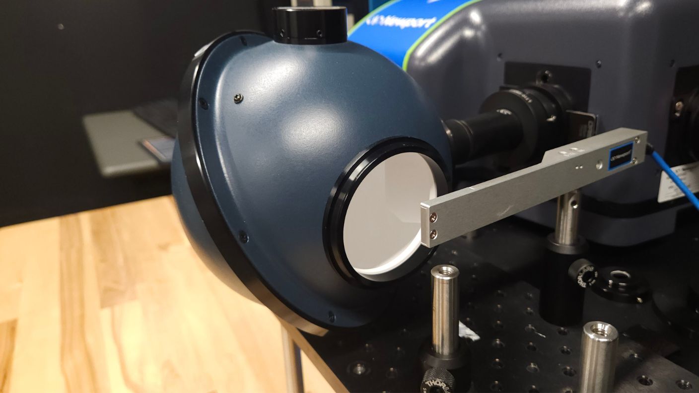
We pipe in a light source. Often, we use halogen because it’s a clean, broadband source. It runs through a filter wheel, narrowing it down to the specific range of light that we're interested in. There are slits so we can cut the actual frequencies down to about plus or minus ten nanometers or five nanometers in the wavelength. It is then redirected into an integrating sphere or similar tool to diffuse the field.
We are then able to concurrently measure the device under test and compare it to a reference device or silicon photo diode.

Polychromator
A polychromator is an optical device that is used to filter light into different bands to isolate parts of the spectrum of the light. Its job is to simulate different lighting conditions.
We use a light source which utilizes an array of different LEDs so that it can control different light bands. It then pipes them into a device that filters and integrates them with a port so that you can read in front of them.
This system allows us to simulate various types of visible lighting—such as fluorescent, cold white LED, or virtual compact fluorescent—as well as standardized illuminants like A, B, C, and D65. We can also simulate displays (e.g., RGB screens) or focus on a selected spectral wavelength.
The control software for the polychromator lets us set it to different types of sources. Once you set the target, the polychromator will adjust its micro mirrors and intensities to simulate that exact light source.
Light Sensor Calibration
One way to ensure that we build units consistently is to use a light sensor calibration station. This station is built to create a controlled environment for light so that we can calibrate every device to read the same values.
We start with a controlled light source. The range of interest we have is all the way from UV to infrared. UV to infrared is hard to get with a single light source, so we use xenon arc. This supports it best with some filters applied to calm down the infrared range and includes the option to add neutral density filters.
The challenge with xenon arc is that it is particularly susceptible to power fluctuations and to vibration due to the nature of how that arc is created. For this reason, we set everything on an optical table to isolate vibrations from going into the lamp. The table is pneumatically suspended and weighs about 2000 pounds. It has multiple air regulators to make sure that it stays level. If you put pressure on one side, say by leaning on it, the entire table will equalize, pneumatically leveling it.

The xenon arc broadband light source pipes light into a dark box so we can isolate out stray light. We also have neutral density filters inside so that we can attenuate the light to the level we want.
The light passes into an integrating sphere. The sphere has two jobs.
- One: to diffuse the light so that you don't have it focus on any given point, creating a nice even lighting no matter what your position.
- Two: to have more than one device monitoring at the same time. We mount the device that we're testing and a photo diode, which monitors the light levels to make sure we have no fluctuations.
We put the reference and the device under test in the same location with kinematic mounts so we can swap them in and out and measure their light levels. We log the data coming off the device to test for any fluctuations or issues with the light that would invalidate the calibration. Depending on how intense we need the light to be, we use a neutral density filter to control the level of the light field. 
As an aid to the operator, we also chart the output of the photodiode over time to monitor the stability and level of the light field.
We have software to process the output values from our sensors, run the ratios between them, calibrate the systems, make sure the firmware is updated, and check that there are not any issues with the device we've built.
The core purpose of the station is to ensure we build the same device each time. Without calibration and due to the small size of the sensor packages, the sensors can have a variation of as much as 25%. In this case, we bring them together to get it down to +/-3% accuracy.
Learn more about Sherpa Product Development Services.
