Or How I learned to love talking to machinists
Designing parts for CNC (Computer Numerical Control) machining involves understanding the capabilities and limitations of the CNC process, as well as optimizing designs for efficient manufacturing. This guide will provide an overview of some best practices for designing parts intended for CNC machining that we have developed and learned at Sherpa.
Understanding CNC Machining
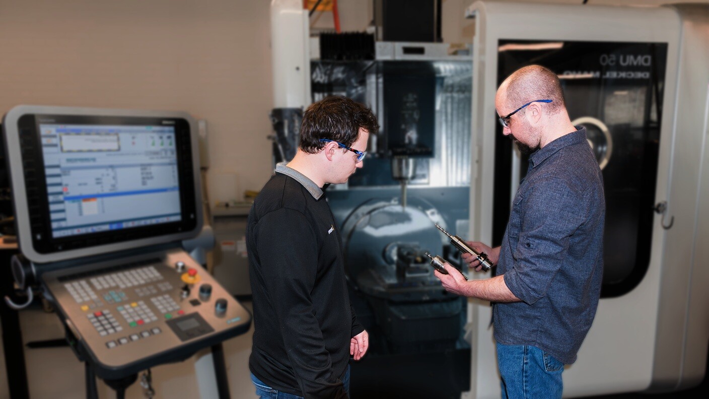
CNC machining is a subtractive manufacturing process that utilizes computer software to drive machinery and tools with a program developed by a machinist. It is commonly used for producing high-precision metal and plastic parts, and modifying or creating higher tolerance features on additively produced parts. CNC offers versatility, accuracy, and repeatability in manufacturing.  Stock material loaded and ready to machine.
The process starts with a piece of stock material whose size and volume are derived from the 3D CAD file (or drawing) for the finished part. Factors taken into consideration by the programmer/machinist that drive cost and quality include:
- Which machine is best suited to produce the part? Vertical or horizontal mill, lathe, mill-turn machine, EDM, etc.
- How many are needed? Is this a production part or prototype quantity? Is it likely to move into production quantities later?
- What is the most efficient stock size to use to minimize machining time and hit the tolerance requirements? Is it available and cost effective?
- What cutting tools are needed to produce the part? Is a custom cutter needed to produce the features or do it in the most cost-effective way? Are non-standard cutters available and cost effective?
- How many operations (setups) will it take to produce the part depending on machine capabilities?
- How will we hang onto the part? Vise, custom fixturing, soft-jaws, (which takes time and money to develop), tape, tabbing, etc. Can we nest multiple parts per setup to maximize spindle time (see fixturing above).
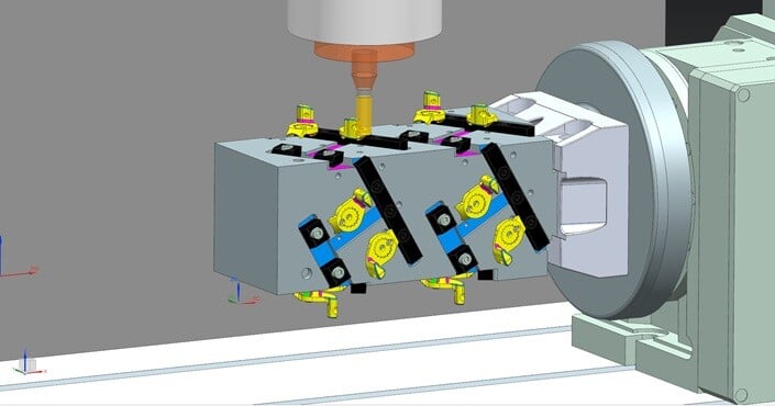
Multiple parts nested on custom 4th-Axis fixture
As a designer it is in your best interest to learn as much as you can about how the end part is, or can be, best produced. Talk to experienced machinists and try to learn from their knowledge of parts they’ve seen over time; the good, the bad, and the ugly. The more you understand about tool reach, work-holding strategies, and the various cutter geometries available, the better part designs you can deliver. They can also familiarize you with which tool manufacturers they prefer or use in the shop further refining the types of feature parameters to consider.
Design Considerations
When designing parts for CNC machining, several key considerations should be kept in mind to optimize the manufacturability and functionality of the final product. These considerations include:
Material Selection
- Choosing the right material is crucial for the performance and characteristics of the CNC machined part. Common materials used in CNC machining include aluminum, steel, titanium, brass, and various plastics. The material properties, such as strength, thermal conductivity, and machinability, should align with the part's intended function.
- Research your material and be sure to note if water based (versus oil based) coolants must be used. Some plastics do not agree with all machine coolants. This can drive cleaning requirements for the shop.
- Many shops have an aversion to machining magnesium (due to it’s risk of dangerous flammability and chip disposal), and composites (fiberglass, carbon fiber, and Garolite) due to the mess created when machining. Confirm the shop's ability and additional costs to run these sorts of finicky materials.
- Is your material (or required finishing like paint, powder coat, anodize, etc) readily available as a stock size? Check the McMaster catalog as a starter. If not, consider the additional time and costs needed for a shop to procure a custom Mill run order.
Geometric Complexity
 The complexity of the part's geometry affects machining feasibility and cost. Simple, well-defined geometries with clear tool paths are generally more efficient to machine. Avoiding intricate features or tight tolerances that may require specialized tooling will contribute to cost-effective manufacturing.
- While 5+ axis machining has reduced the number of setups a part may need, not all shops have these machine tools yet.
Tolerances and Surface Finishes
- Understanding the required tolerances and surface finishes is crucial for achieving the desired part functionality. Tighter tolerances and finer surface finishes may require additional machining operations, impacting both cost and lead time.
- If features/faces do not need to perform sealing or flatness functions, consider allowing tool marks or looser roughness, very loose tolerance, mill finish, etc.
- Be aware of what your default drawing tolerance block states and dimension/tolerance accordingly.
Design for Manufacturability (DFM)
- Utilizing Design for Manufacturability (DFM) principles ensures that the part can be accurately and efficiently machined. This includes considerations such as minimizing the number of setups, choosing appropriate tool paths, and optimizing the part orientation to reduce machining time and complexity.
- TALK TO MACHINISTS. They have valuable knowledge and experience that can help you make better decisions in CAD resulting in cost savings.
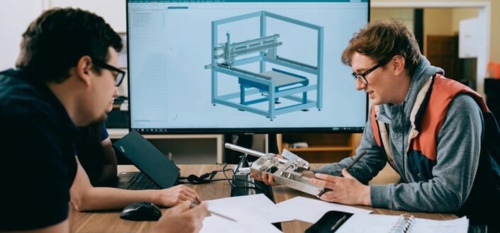 Engineers holding design review for manufacturability
 Design Guidelines
Based on the insights and experiences of our team, here are some tips to better design for CNC machined parts.
- Optimize for Tool Access: Design features that allow for efficient tool access, enabling the use of standard cutting tools and reducing the need for complex tooling setups. Complex angles are challenging to machine and inspect, and will drive up costs. Most CNC machines need extended access to create features so don’t limit that with blocking geometry or material overhangs.
 Minimize Sharp Internal Corners: Avoid sharp internal corners to facilitate tool movement and prevent tool breakage, which can impact both machining quality and tool life. Add a corner drill hole (Fig.1) to maintain perpendicular faces if a fillet won’t do.
Figure 1: Corner Drill Hole- Minimize radiused external edges: It’s easy to put a fillet on an edge in the CAD model. It can look prettier that way. However, that translates to a lot of extra programming and machining time (aka $$$). If you just need finished part edges to not cut or scratch people/wires/etc. consider specifying “break sharp edges” to reduce costs or consider tumbling the parts to remove sharps.
- Consider Material Grain Orientation: Understand how the material's grain direction may influence machinability and structural integrity, especially for metals like aluminum and steel. If grain direction matters, clearly communicate it on the drawing or with PMI notation.
- Consider machining cutter mark direction for vacuum seals: Machine cutters do not leave a mirror perfect finish without attention by the machinist or post-op finishing. If a sealing surface, like o-ring or gasket mating interfaces, are critical (e.g. high vacuum applications) annotate the feature surface and indicate which direction machining marks are not permitted to go to ensure no tiny phantom leaks occur. Something like “No Radial finish marks permitted in this region”.
- Use Symmetry and Balance: Design parts with symmetry and balance to minimize tool movement and setups, promoting efficient machining and consistent quality. Consider how the machinist will hold onto the part in the CNC machine; can they use a vise or will custom work-holding be necessary?
- Integrate Smart Machining Features: Incorporate standard features such as fillets, chamfers, and standard hole sizes to streamline machining operations and reduce custom tooling requirements. Research standard radii on ball mill cutters for easy floor-wall fillet creation, chamfer cutter tools, etc and try to choose one that is off the shelf in nature.
- Use Nonstandard Corner Radii for large cavities: Radii between walls can be sized up in order to facilitate using the largest diameter cutter and continuous cutting for mass material removal. Think large pocket areas, box regions, mold cavities, etc. If the corner radius is same size as cutter radius you can get unexpected results when a large percentage of the cutter engages with the material. Try for 20% to 40% larger than the cutting tool to get rid of chatter in corners.


Figure 2: Oversize corner fillets slightly to allow continuous machining with the largest possible cutter - Consider stock size/shape: Can the part use standard sized material stock effectively to reduce waste, and is the stock size readily available? Consider using round bar stock to reduce overall material removal as well. If you are removing a lot of material, consider an assembly of parts to reduce wasted chips and machining time.
- Consider Unknown Needs of Prototyping: For prototyping or low-volume production, design parts with simplicity and ease of modification in mind, enabling cost-effective iterations and design improvements. You may find you need to add a hole during the first build. It's inexpensive to include an extra hole or two for cable routing, zip tying wire bundles, etc. This could help avoid the need to disassemble the system, remove and rework the part.
- Feature Size and Orientation: Design features with consideration for feature size, orientation, and aspect ratios to optimize machining stability and surface finish quality.
- Thin wall features: Tall and/or thin-walled features can pose machining challenges and maintain desired tolerances or surface finish. Consider material removal procedures a machinist might need to take to produce the desired feature. Add bracing, omit holes in thin walls to reduce distortion, etc.
 Hole size and depth: Generally, 10x hole diameter is the deepest a machinist can deliver without issue. (e.g. a 0.50” diameter hole should not be deeper than 5-inches). Some CAD packages like to “add hole edge chamfers” by default; these can become costly so watch what your defaults do during feature creation.
Figure 3: Expensive hole option - Determine Appropriate Tolerance Requirements: Collaborate with the machining supplier to establish appropriate tolerance requirements, balancing precision with cost-efficiency. Ensure the tolerances you specify are really necessary to part function to keep machining costs down. Establish your tolerance datum reference system to best enable measuring the features and tolerances you specify.
- Consider end-machining process while designing: Is this part going to be turned on a lathe, milled on a vertical or horizontal mill, or will it leverage both with a mill-turn machine? Align your design decisions and understand the capabilities and limitations of each type of machine early on. Get to know the manufacturing capabilities of each type of machine and collaborate with suppliers.
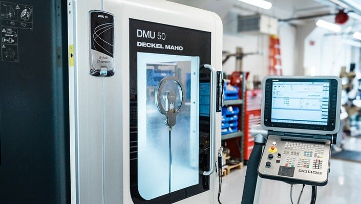 DMU 50 - 5-Axis CNC Machine
Conclusion
Designing (well) for CNC machined parts involves a multifaceted approach that integrates engineering principles, material science, and manufacturing expertise. By considering the aforementioned design considerations and guidelines, engineers and designers can create optimized designs that enhance the manufacturability, quality, and cost-effectiveness of CNC machined parts.
It is always best to request feedback from reliable shops on your designs. This will ultimately result in getting high value parts in return and extend your manufacturing knowledge as a designer/engineer. Vertically integrated design and manufacturing companies need to leverage their in-house machining knowledge often. Things can look great on the screen in CAD but collaborative machinists add a lot of value to delivering the best part for the need.
Need CNC work? Check out our in-house machine shop.