Building a portable wall system to protect from RF bombardment
The Client
Rohde & Schwarz is a top global manufacturer of test and measurement, secure communications, monitoring and network testing equipment.
One of their customers needed to provide a large-scale test system to validate their fighter jets would not be adversely affected by military strength radar in the Asia Pacific region. The tests were to bombard the aircraft with high levels of microwave/RF to ensure they still function. RF at high levels can be harmful to people, so they needed to provide an outdoor microwave absorbing ‘backstop’ to protect those nearby.
The Challenge
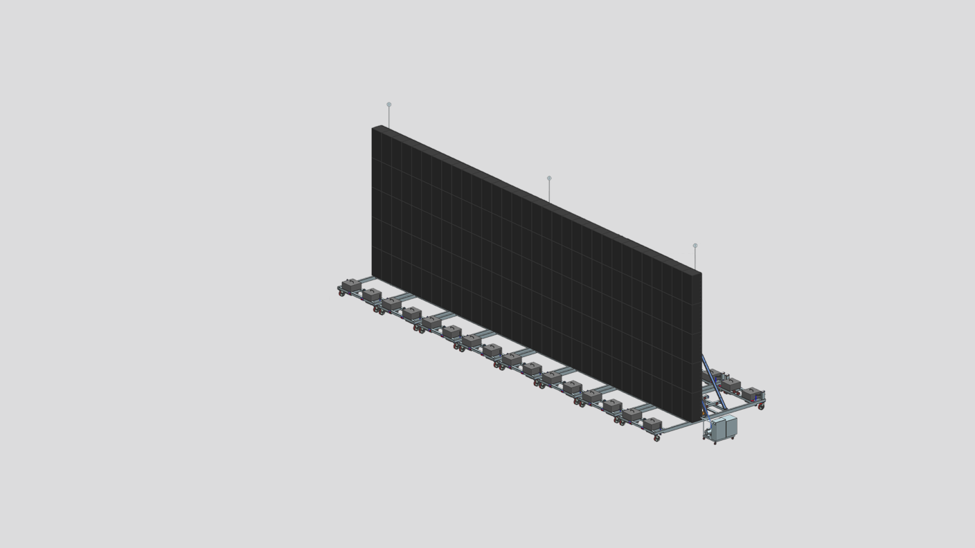
They came to Sherpa to enlist our design and build support to create a wall structure that was 60 feet long and 20 feet high. Designed for absorbing microwave testing outdoors, the wall had to withstand harsh weather in a coastal location, while being a temporary structure that can be moved and stored when not in use.

Our approach
In our early concepting we looked at climbing walls for reference, some of which are setup outdoors for training. We reviewed the size and weight of the blocks that needed to be on the wall to provide the RF protection. We determined the best mechanical system to allow for the wall to be raised and lowered and stored. We examined the wind and potential snow impact as the wall would essentially act as a sail when erected. In all these considerations we had to think about making the entire structure packable so it could be transported.
Wall Components
The wall would use custom designed RF absorbing blocks, 2ft x 2ft x 4ft each, made of microwave absorbing foam internally and rubber outside to withstand the outdoor use. The design solution involved eight individual wall sections that could be positioned tightly side by side and still be storable in four shipping containers. Welded tube and structural plate components comprised the majority of the structure.

Based on the block size, 160 RF absorbing blocks were required to cover the wall. Each section of the wall was hinged and designed to be loaded with the blocks in the lowered position. The blocks had special hanging features that needed to be correctly aligned, and the top rows of blocks were removed when stored in the shipping containers.
Each wall segment utilized hydraulic cylinders to tilt the wall up which was then braced in position for use. We had to determine the lifting force required, and an easy to assemble method to position the bracing. Once fully upright and locked, the wall sections stay in place so the hydraulics are only needed for raising and lowering the sections. We designed a single hydraulic pump cart to lift each section, disconnecting and reconnecting it as the wall was built out. This saved money and storage space.

Environmental Considerations
Once the wall was upright, it would act like a sail and needed to be able to handle the wind load. The client gave us a wind requirement for the expected environment. We used predictive engineering to perform FEA on the wall design. Those results fed design changes, including adding bracing for the two configurations (upright and storage bracing) and cast concrete counterweights on corners.
See full FEA Report
We ensured bracing could handle snow weight accumulation and added mounting for custom lightning rods.

Everything was stored in 4 containers, including the wall sections, the 160 blocks, the hydraulic lift, concrete forms for the ballast, and all the bracing. All of our CAD design work was done using NX to verify the fit and function.
Construction of the Wall
Once the design and analysis was finished, we worked with a large steel fabrication vendor, Peninsula Iron Works, to build out the wall. Protoyping is always valuable so we built a single wall section to begin. During the test raise we found that the bearing blocks did not have a strong enough housing and one cracked. We tried to find an off the shelf bearing with a stronger case but could not. We designed a custom bearing block from steel and manufactured a test set in our machine shop. The new bearings worked great, so we machined and assembled the rest needed in-house. The remainder of the sections were built and painted to the customers color requirements.
We conducted a number of assembly and storage tests in the back parking lot of our offices to validate the design with the customer. After a few more minor tweaks the final components including all wall sections, hydraulic pump and extra oil, the forms for casting the counterweights, and the RF blocks were packed up and ready to ship overseas. Riggers picked up the containers and they were on their way.
It was setup, tested and put away successfully at the test site. The customer said this was one of their largest test systems produced to date.
